Dependencies
Understanding dependencies
A schema contains collections of tables of related data. Accordingly, entities in one table often derive some of their meaning or context from entities in other tables. A foreign key defines a dependency of entities in one table on entities in another within a schema. In more complex designs, dependencies can even exist between entities in tables from different schemas. Dependencies play a functional role in DataJoint and do not simply label the structure of a pipeline. Dependencies provide entities in one table with access to data in another table and establish certain constraints on entities containing a foreign key.
A DataJoint pipeline, including the dependency relationships established by foreign keys, can be visualized as a graph with nodes and edges. The diagram of such a graph is called the entity relationship diagram or Diagram. The nodes of the graph are tables and the edges connecting them are foreign keys. The edges are directed and the overall graph is a directed acyclic graph, a graph with no loops.
For example, the Diagram below is the pipeline for multipatching experiments
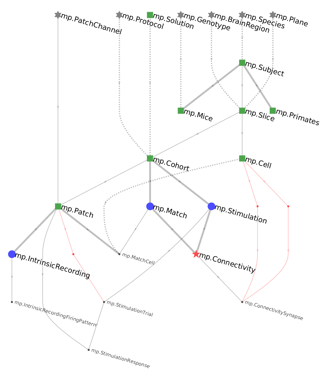
The graph defines the direction of the workflow. The tables at the top of the flow need to be populated first, followed by those tables one step below and so forth until the last table is populated at the bottom of the pipeline. The top of the pipeline tends to be dominated by lookup tables (gray stars) and manual tables (green squares). The middle has many imported tables (blue triangles), and the bottom has computed tables (red stars).
Defining a dependency
Foreign keys are defined with arrows -> in the table definition,
pointing to another table.
A foreign key may be defined as part of the primary-key.
In the Diagram, foreign keys from the primary key are shown as solid lines. This means that the primary key of the referenced table becomes part of the primary key of the new table. A foreign key outside the primary key is indicated by dashed line in the ERD.
For example, the following definition for the table mp.Slice has three foreign keys,
including one within the primary key.
# brain slice
-> mp.Subject
slice_id        : smallint       # slice number within subject
---
-> mp.BrainRegion
-> mp.Plane
slice_date        : date                 # date of the slicing (not patching)
thickness         : smallint unsigned    # slice thickness in microns
experimenter      : varchar(20)          # person who performed this experiment
You can examine the resulting table heading with
mp.BrainSlice.heading
The heading of mp.Slice may look something like
subject_id      : char(8)        # experiment subject id
slice_id        : smallint       # slice number within subject
---
brain_region        : varchar(12)        # abbreviated name for brain region
plane               : varchar(12)        # plane of section
slice_date          : date               # date of the slicing (not patching)
thickness           : smallint unsigned  # slice thickness in microns
experimenter        : varchar(20)        # person who performed this experiment
This displayed heading reflects the actual attributes in the table. The foreign keys have been replaced by the primary key attributes of the referenced tables, including their data types and comments.
How dependencies work
The foreign key -> A in the definition of table B has the following effects:
- The primary key attributes of
Aare made part ofB's definition. - A referential constraint is created in
Bwith reference toA. - If one does not already exist, an index is created to speed up searches in
Bfor matches toA. (The reverse search is already fast because it uses the primary key ofA.)
A referential constraint means that an entity in B cannot exist without a matching
entity in A.
Matching means attributes in B that correspond to the primary key of A must
have the same values.
An attempt to insert an entity into B that does not have a matching counterpart in
A will fail.
Conversely, deleting an entity from A that has matching entities in B will result
in the deletion of those matching entities and so forth, recursively, downstream in the
pipeline.
When B references A with a foreign key, one can say that B depends on A.
In DataJoint terms, B is the dependent table and A is the referenced table
with respect to the foreign key from B to A.
Note to those already familiar with the theory of relational databases: The usage of the words "depends" and "dependency" here should not be confused with the unrelated concept of functional dependencies that is used to define normal forms.
Referential integrity
Dependencies enforce the desired property of databases known as
referential integrity.
Referential integrity is the guarantee made by the data management process that related
data across the database remain present, correctly associated, and mutually consistent.
Guaranteeing referential integrity means enforcing the constraint that no entity can
exist in the database without all the other entities on which it depends.
An entity in table B depends on an entity in table A when they belong to them or
are computed from them.
Dependencies with renamed attributes
In most cases, a dependency includes the primary key attributes of the referenced table as they appear in its table definition. Sometimes it can be helpful to choose a new name for a foreign key attribute that better fits the context of the dependent table. DataJoint provides the following projection syntax to rename the primary key attributes when they are included in the new table.
The dependency
-> Table.project(new_attr='old_attr')
renames the primary key attribute old_attr of Table as new_attr before
integrating it into the table definition.
Any additional primary key attributes will retain their original names.
For example, the table Experiment may depend on table User but rename the user
attribute into operator as follows:
-> User.proj(operator='user')
In the above example, an entity in the dependent table depends on exactly one entity in
the referenced table.
Sometimes entities may depend on multiple entities from the same table.
Such a design requires a way to distinguish between dependent attributes having the
same name in the reference table.
For example, a table for Synapse may reference the table Cell twice as
presynaptic and postsynaptic.
The table definition may appear as
# synapse between two cells
-> Cell.proj(presynaptic='cell_id')
-> Cell.proj(postsynaptic='cell_id')
---
connection_strength : double  # (pA) peak synaptic current
If the primary key of Cell is (animal_id, slice_id, cell_id), then the primary
key of Synapse resulting from the above definition will be (animal_id, slice_id,
presynaptic, postsynaptic).
Projection always returns all of the primary key attributes of a table, so animal_id
and slice_id are included, with their original names.
Note that the design of the Synapse table above imposes the constraint that the
synapse can only be found between cells in the same animal and in the same slice.
Allowing representation of synapses between cells from different slices requires the
renamimg of slice_id as well:
# synapse between two cells
-> Cell(presynaptic_slice='slice_id', presynaptic_cell='cell_id')
-> Cell(postsynaptic_slice='slice_id', postsynaptic_cell='cell_id')
---
connection_strength : double  # (pA) peak synaptic current
In this case, the primary key of Synapse will be (animal_id, presynaptic_slice,
presynaptic_cell, postsynaptic_slice, postsynaptic_cell).
This primary key still imposes the constraint that synapses can only form between cells
within the same animal but now allows connecting cells across different slices.
In the Diagram, renamed foreign keys are shown as red lines with an additional dot node in the middle to indicate that a renaming took place.
Foreign key options
Note: Foreign key options are currently in development.
Foreign keys allow the additional options nullable and unique, which can be
inserted in square brackets following the arrow.
For example, in the following table definition
rig_id  : char(4)   # experimental rig
---
-> Person
each rig belongs to a person, but the table definition does not prevent one person
owning multiple rigs.
With the unique option, a person may only appear once in the entire table, which
means that no one person can own more than one rig.
rig_id  : char(4)   # experimental rig
---
-> [unique] Person
With the nullable option, a rig may not belong to anyone, in which case the foreign
key attributes for Person are set to NULL:
rig_id  : char(4)   # experimental rig
---
-> [nullable] Person
Finally with both unique and nullable, a rig may or may not be owned by anyone and
each person may own up to one rig.
rig_id  : char(4)   # experimental rig
---
-> [unique, nullable] Person
Foreign keys made from the primary key cannot be nullable but may be unique.